XSCHEM ELEMENTS
WIRES
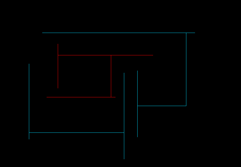
Wires in XSCHEM are the equivalent of copper traces in printed circuit boards or electrical conductors. Wires are drawn as lines but the electrical connectivity graph is built by XSCHEM. To draw a wire segment point the mouse somewhere in the drawing window and press the 'w' key. A rubber wire is shown with one end following the mouse. Clicking the left mouse button finishes the placement. The following picture shows a set of connected wires. There are many wire segments but only 3 electrical nodes. XSCHEM recognizes connection of wires and uses this information to build up the circuit connectivity. All wires are drawn on the 'wire' layer. One electrical node in the picture below has been highlighted in red (this is a XSCHEM function we will cover later on).
LINES
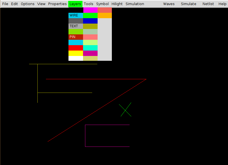
Lines are just segments that are used for drawing. Lines do not have any electrical meaning, in fact when building the circuit netlist, lines are completely ignored. XSCHEM uses different layers to draw lines. Each layer has its own color, allowing to draw with different colors. Lines are placed like wires, but using the 'l' key. The 'Layers' menu allows to select various different layers (colors) for the line.
RECTANGLES
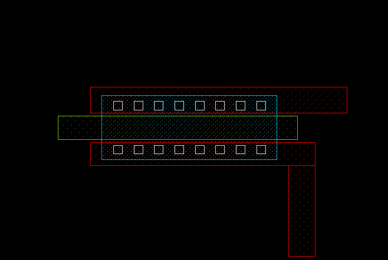
Rectangles like Lines are drawable on multiple layers, and also do not carry any electrical information. A specific 'PIN' layer is used to make pins that are used to interconnect wires and components. Different fill styles (or no fill) can be defined for each layer. Rectangles are placed with the 'r' bindkey
POLYGONS
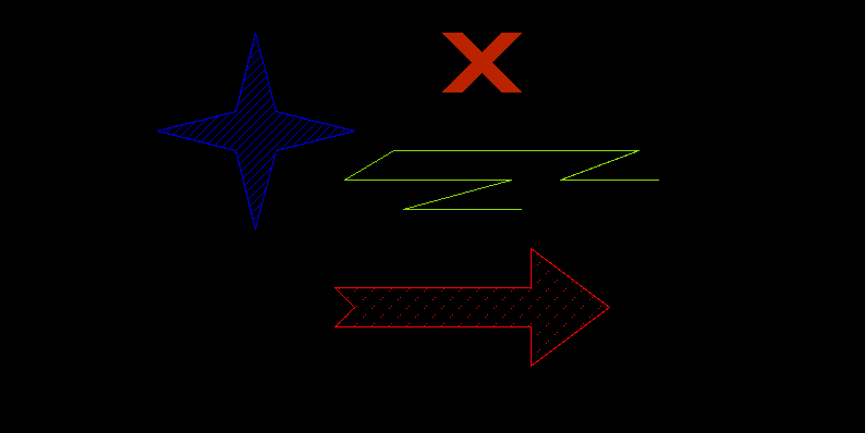
Polygons are paths that can be drawn on any layer. Placements begins with the 'ctrl-w' key and continues as long as the user clicks points on the drawing area. Placement ends when:
- the last point is coincident to the first point.
- or by clicking the right mouse button, for an open polygon.
- or by hitting the Return key, for a closed polygon (this can be done also by clicking the last point coincident to the first polygon point).
CIRCLES / ARCS
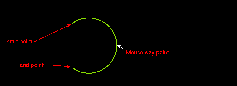
Arcs may be placed by hitting the Shift-C key. First click the start point, then the end point.
Moving the mouse will show the arc passing thru the 2 points and the mouse waypoint.
Clicking will place the arc.
Arcs may be modified after creation by selecting in stretch mode ( Ctrl-Button1-drag ) one of the arc ends
or the arc center:
- (end point selected in stretch mode): by starting a move (m)
operation and moving the mouse the arc sweep may be changed.
- (start point selected in stretch mode):by starting a move (m) operation and moving the mouse the start arc angle may be changed.
- (arch center selected in stretch mode): by starting a move (m) operation and moving the mouse the arc radius may be changed.
If a circle is needed then use the Ctrl-Shift-C key combination.
TEXT
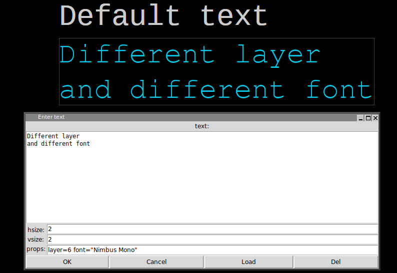
Text can be placed with the 't' bindkey. A dialog box appears where the user inputs the text and text size.
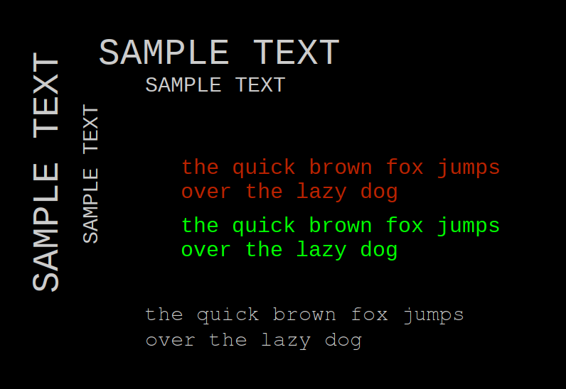
The layer property can be used to draw text on a different layer, for example, setting layer=6 will draw on cyan color. A font property is defined to change the default font. Use only Monospaced fonts because bounding box is not correctly calculated by XSCHEM for proportional typefaces. You wil learn in the xschem properties chapter how to set, edit and change object properties.
SYMBOLS
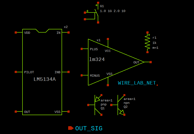
Symbols are graphical elements that represent electrical components. A symbol represents an electronic device, like for example a resistor, a bipolar transistor, an amplifier etc. As you can see graphically symbols are built with lines, rectangles, polygons and texts, the graphical primitives shown before. In the picture below some components are placed in a schematic window. Components are instances of symbols. For example you see three placements of the 'npn' bipolar transistor symbol. Like in C++, where objects are instances of classes, here components are instances of symbols.
Symbols (like schematic drawings) are stored in xschem libraries. For XSCHEM a library is just a directory placed under the XSCHEM_LIBRARY_PATH directory, see the installation slide. A symbol is stored in a .sym file.
user:~$ cd .../share/xschem/xschem_library/
user:xschem_library$ ls
devices
user:xschem_library$ cd devices
user:devices$ ls *.sym
ammeter.sym                generic.sym            noconn.sym             switch_hsp.sym
arch_declarations.sym      gnd.sym                npn.sym                switch.sym
architecture.sym           ind.sym                opin.sym               title.sym
assign.sym                 iopin.sym              package_not_shown.sym  tline_hsp.sym
attributes.sym             ipin.sym               package.sym            use.sym
bus_connect_not_shown.sym  isource_arith.sym      param_agauss.sym       vccs.sym
bus_connect.sym            isource_pwl.sym        param.sym              vcr.sym
capa.sym                   isource.sym            parax_cap.sym          vcvs.sym
cccs.sym                   k.sym                  pmos3.sym              vdd.sym
ccvs.sym                   lab_pin.sym            pmos4.sym              verilog_delay.sym
connect.sym                lab_wire.sym           pmosnat.sym            verilog_timescale.sym
delay_hsp.sym              launcher.sym           pnp.sym                vsource_arith.sym
delay_line.sym             netlist_at_end.sym     port_attributes.sym    vsource_pwl.sym
delay.sym                  netlist_not_shown.sym  res.sym                vsource.sym
diode.sym                  netlist.sym            spice_probe.sym        zener.sym
flash_cell.sym             nmos3.sym              spice_probe_vdiff.sym
generic_pin.sym            nmos4.sym              switch_hsp_pwl.sym
user:devices$ cd ...share/doc/xschem/
user:xschem$ ls
examples  pcb
To place a symbol in the schematic window press the 'Insert' key. A file chooser pops up, go to the xschem devices directory (.../share/xschem/xschem_library/devices in the distribution by default) and select a symbol (res.sym for example). The selected symbol will be instantiated as a component in the schematic at the mouse pointer coordinates.