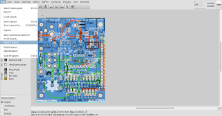
The new formats are accessible through the usual export menu:
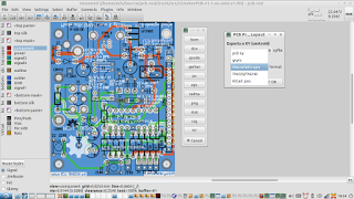
with which selection of the "XY" format presents the XYRS export format options and units for export:
For those keen to export a custom format, any new format can be defined in the following file:
pcb-rnd/trunk/src_plugins/export_xy/default_templ.h
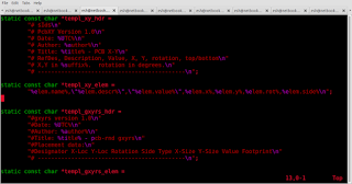
The format is pretty self explanatory. The user simply needs to choose a new name for the export type, create suitable text header fields, and then decide on the order of exported values, and their separator.
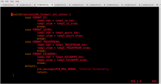
Following this, the new exporter type must be added to the existing structure in the xy.c file
pcb-rnd/trunk/src_plugins/export_xy/xy.c

and then, to make the new exported format active, it has to be added to the switch statement further down in xy.c :
If ./configure has not already been run previously in pcb-rnd/trunk it will need to be run, after which
make
in
pcb-rnd/trunk
is all that is needed to make the changes active.
Alternatively, if you have an example of a format you would like implemented in the exporter, someone on IRC will be able to help you implement it.
After Macrofab, TM220 and TM240 export were added to the exporter, KiCad .pos format was also implemented as a quick and easy demonstration of the template based configuration, and, as a bonus, allow the use of scripts written by KiCad users for further customisation of position files for multiple reel pick and place machines.
The OpenPnP project can use ordinary xyrs and KiCad .pos files, so pcb-rnd users should have no difficulty using OpenPnP software.
The default xyrs outputs and .pos outputs are also suitable for assemblers such as SmallBatchAssembly.
The main differences to note between formats
The only other cautionary note is that some default footprints may not adhere to the usual conventions relating to rotation and centroid, i.e. pin 1 should be at the top or top left, and the coordinate centroid for the footprint should indeed be the centroid of the element.
Finally, if your default footprints' description and value fields are transposed, the exported xy file will also have these values transposed. As always, the quality of your final PCB will depend on the validity of the footprint elements you use.