|
|
Glossary
- rfp: Recommended FootPrint; there is dimensioned a drawing of copper pads
- ipc: there is a dimensioned (and toleranced) mechanical drawing of the component; copper pad dimensions are derived using methods from IPC-7351
- vendor-*: bedrock-rnd collection of rfp and ipc footprints identified by vendor-specific package names; each vendor have their own internal package naming convention and the internal package name is usually mentioned in the datasheet
- standard-*: bedrock-rnd collection of rfp and ipc footprints identified by their standard package name, e.g. SOT23 or TO-220 from JEDEC, IEC, etc.
- datasheet-*: generic parametric footprints; pick a footprint, copy a few dimensions from the datasheet and get a footprint that works best with that specific product; use -rfp with the recommended footprint drawing or -ipc with the component drawing
Click on the flowchart to enlarge.
Naming, aliases
Aliases following the IPC-7351 recommended footprint names (e.g. RESC3216 for
chip resistor metric size 3216) are also included. For imperial size use
an I prefix, e.g. IRESC1206.
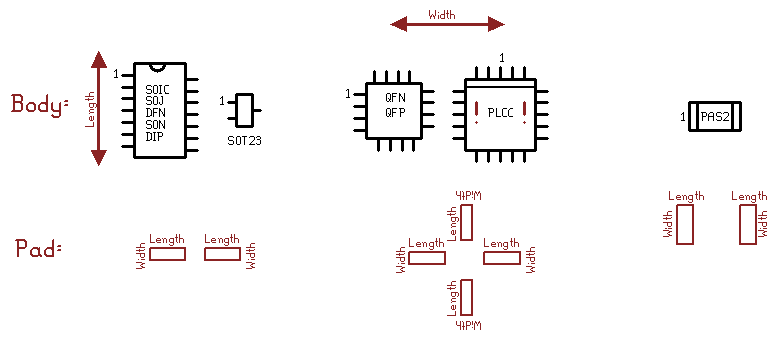
Orientation, length, width
The standard orientation (0 degree rotation) is pin 1 on the left (west) side,
at the top (north), when the part is looked at from the top side. The only
exception is PLCC, which, for historical reasons, has pin 1 in the middle
of a row of pins, and happens to be on the middle north.

In the standard orientation package/body length is a vertical (north-south)
measure and package/body width is a horizontal (east-west) measure. Pads
are measured orthogonally: pad length is horizontal (east-west) and pad
width is vertical (north-south). The standard pad rotation 0 is on the left
(east) side of any component; other pads around the component are normally
derived from the standard pad by rotating 90, 180, 270 degrees.
Dimension syntax
| example | explanation
|
|---|
| 12.34 | exact or basic value, in mm
| | 12.34unit | exact or basic value, with unit (e.g. mm, mil, inch)
| | 12.34+-0.5 | nominal value with symmetric tolerance, in mm
| | 12.34+-0.5unit | nominal value with symmetric tolerance, with explicit unit
| | 12.34~56.78 | minimal and maximal value specified, in mm
| | 12.34~56.78unit | minimal and maximal value specified, with explicit unit
|
Component drawing values (body dimensions, pin/lead sizes and positions) are
typically coming with tolerances, except for a few values marked as basic
in the datasheet. Footprint (copper pad) dimensions are exact (basic)
values.
Parameter naming conventions
When dimensions are specified, main dimension parameter names are derived as
follows.
BL, BW: body length, body width; dimensions of the plastic body.
PE: Pin (or pad) extent is measured from side to side between the
outer points of the pins (or pads).
PG: Pin (or pad) gap is the empty, no-copper distance between pins
(or pads) on the opposite side.
PP: Pin (or pad) pitch is the distance between the imaginary
centerlines of adjacent pads on the same side, pretending a package of
the same style with no missing pads (e.g. 6 pads in case of a sot23
package).
PRP: Pin (or pad) row pitch is the distance between the imaginary
center points of pads on opposite side. In other words, the distance between
the center lines of rows of pads on opposite sides. For example the PRP
for a SOIC is a horizontal measure and is a value halfway between PE and PG.
PC: Pin (lead) contact length is the length dimension along which a
pin or lead is in contact with the copper pad.
Square vs. rectangular components
When a component has pins/leads/pads on more than 2 sides, typically 4 sides,
such as QFN, QFP or PLCC, the component body is either square or rectangular.
For a square useful overall dimension parameters are:
- BS instead of BL and BW
- PE
- PRP
- PG or PC
For a rectangular useful overall dimension parameters are:
- BL and BW instead of BS
- PEL and PEW instead of PE
- PRPL and PRPW instead of PRP
- PGL and PGW instead of PG
- or PC, because it is assumed to be uniform along all edges
In other words, in square case there's a single value for some dimensions
while in rectangular case the dimension is split into (body) length and
(body) width directions, parameters suffixed with L and W accordingly.
|
![[bedrock-rnd logo]](../resources/logo128tr.png)
![[bedrock-rnd logo]](../resources/logo128tr.png)