pcb-rnd knowledge pool
ddraft: measuring out numeric coords
| ddraft_sot23 by Tibor 'Igor2' Palinkas on 2021-10-21 | Tags: howto, ddraft, measure, dimensions, place |
Abstract: Demonstrate how to use ddraft to measure out fixed points in space given by numeric coords. The example is placing the pads for a sot23 accurately.
Step 1: preparation
These were done before the video.
First we need a land pattern for sot23:
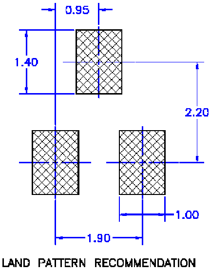
Create the required padstack, an 1mm * 1.4mm rectangle.
Plan the placement: we would start from bottom left pad's center - this will be our base point, we measure everything else from here. Bottom right pad's center is easy: a horizontal movement of 1.9mm from our base. The top center pad is 2.2mm above the base point, which is a movement of -2.2mm vertically. Horizontally it's halfway so 1.9mm / 2 = 0.95mm from the base.
Tune the drawing style so line thickness is much thinner than the default - something like 0.02mm is reasonable for this scale.
Step 2: grid and base point
There are multiple ways achieving our goal with ddraft. What we are going to do in this particular example is draft lines, using line end points as marker for point-of-interest. We also rely on pcb-rnd being able to snap to line end.
For the snap to work best, set grid to 1mm.
Then draw a diagonal line anywhere on the board on a documentation layer (e.g. the top-assy layer). Using a doc layer is good practice: objects drawn on a doc layer will never interfere with copper.
The top right end of this diagonal line will be our base point.
Step 3: measure out the bottom right pad's center
Click on the 2d (ddraft) tool in the toolbar. This will open the CLI on the bottom, with the prompt being "ddraft" which means we need to enter ddraft commands (not pcb-rnd actions). Ddraft employs is a special input method that can combine keyboard input with mouse input and the mouse cursor will snap to objects (unless it is disabled by the user).
Start typing a line drawing command: line from , then hover the mouse cursor to the base point, make sure it is precisely on the endpoint of the line (with 1mm grid it's not too hard to do) and click. This will fill in absolute coords in the command line. So the starting point of the line object is known.
Now to fill in the ending point, we need a relative move to the bottom right pad's center. Which is 1.9mm to the right. So type space, then to rel 1.9mm,0 . This syntax means x,y movement relative to the last point (the starting point in our case). Press enter and the new line appears.
Step 4: measure out the top center pad's center
Press the ':' key to open the CLI again - since the active tool (see the toolbar on the top area) is still ddraft, we get the ddraft prompt again.
Follow step 3 in specifying the starting point of a new line from the base point. The "to" part should be "rel 0.95mm,-2.2mm" , since we need to move halfway in horizontal direction and 2.2mm up. The result is a line connecting our base (bottom left pad center) and the top center pad center.
Step 5: place a padstack on line ends
Now we have 3 points in space marked with line endpoints:
- the base point, which is where our 3 drafting lines share endpoints; this is our bottom left pad center because in step 1 we made this arbitrary choice
- the right end of the horizontal line of step 3 for bottom right pad center
- the top-right end of the long line drawn in step 4, which marks the center of the top pad
All we need to do is copy the padstack (e.g. with ctrl+c) grabbing it by its center and place 3 copies on those line endpoints listed above. As long as the padstack is grabbed by its center with object snap and line-end object snap happens on placement, the result will be accurate to the nanometer.
Step 6: clean up
Set a finer grid and while the doc layer is still active, press the del key over the drafting lines to remove them.
You can also download the finished board file for reference. Note: the padstack is not production-quality, just bare copper and the resulting 3 pads are not converted to a footprint. It's because the goal was to demonstrate how to measure out exact coordinates, not how to draw a valid footprint.