pcb-rnd knowledge pool
Footprints: how to set pick-and-place origin of a subcircuit
| fp_pnp_orig by Tibor 'Igor2' Palinkas on 2020-xx-xx | Tags: howto, pnp, pick, place, pick-and-place, origin, center, diamond, grab |
Abstract: Some footprints are asymmetric or have features on the top so the best point for grabbing them in a pick-and-place machine is not the geometrical center or the point that is practical for grabbing the subcircuit for GUI editing. This howto describes manually setting a differnt pick-and-place origin for those cases.
For this example, we are going to use a stripped down copy of the standard library SOT325 footprint. The library version does have a pick-and-place origin, the stripped down version does not.
This example
SOT325
placed on an
example board
at 200;200mil (grabbing at it's
subc origin, the "diamond" mark) will yield a
We could configure the XY exporter to grab the part at the geometric
center or at the center-of-mass calculated by terminals - but that would
ignore the body of the part, which also changes the center-of-mass.
So the best method is to manually specify the pick-and-place origin point,
which is the point within the subcircuit where the pick-and-place machine
shall grab it.
To modify the footprint, make a copy, e.g.
1. Turn off the visibility of the top silk layer so it won't interfere
2. Increase grid to 0.1mil or finer
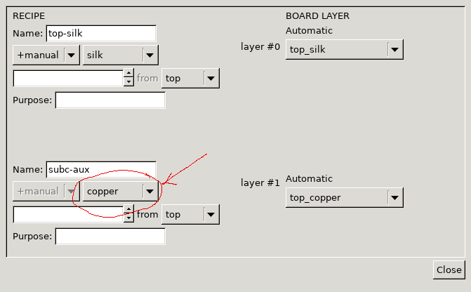
3. Right click on an empty part of the subcircuit, context menu, Edit layer bindings
4. The objects interesting for us are on the subc-aux layer, but that layer is normally invisible; find it in the layer binding dialog and change it from "virtual" to "copper"
(now that the subc-aux layer is the only top copper layer bound, whatever we draw on the top copper layer will end up on the subc-aux layer of the subcircuit)
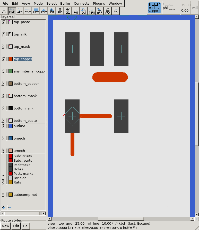
5. Enable orthogonal moves (with pressing {m c o} or from the mode, cursor/snap menu
6. Draw a line starting from the point that should be the pick&place origin, make it at least 25 mil long (the coordinate readout on the top right will help), then press esc to leave the line drawing tool
7. Set back the grid to 25 mil
8. Grab the far endpoint of the line and move it to the starting point, reducing the line length to 0, effectively making it a circle; the 25 mil grid and snapping (default on) will help with this
9. Right click on this point, select the "Edit properties" menu
10. In the property editor dialog that opens, click on the 'add' button
(on the bottom); this will create a new attribute on the zero-length-line object
11. The attribute key should be
subc-role
and the attribute value
should be
pnp-origin
. Warning: these are both case sensitive!
12. Close the dialogs, repeat step 4 and change back the binding of
the subc-aux layer from copper to virtual; this will hide the subc-aux objects
13. Save the footprint (using {f s} or File menu, Save layout).
Now
pnp.fp
contains an extra subc-aux object, which is
a zero-length line with attributes set up so that the XY exporter understands
it marks the pick-and-place point. (In fact the actual point is the middle of
the line, but as the line is zero length, it's the same as the start and
end point of the line.) If you reproduce the same
example board
with pnp.fp placed at 200;200 mil this time,
then do the same
XY export
the new coordinates will
be 225.60,4842.00 mil, which is slightly right and slighlty up to the original
point - right where we placed the subc-origin point within the footprint.
cp plain.fp pnp.fp
and open that file with pcb-rnd. That will get you the "footprint editor",
which is really jsut pcb-rnd with loose-subc enabled, saving footprints instead
of whole boards. Then add the pick-and-place origin object, following
these steps.