pcb-rnd knowledge pool
Using the asm assembly plugin for manual assembly
| asm_tutorial by Ronald 'Miloh' Alexander on 2019-08-12 | Tags: tutorial, assembly, assemble, soldering, solder, populate, select, build, manual |
Abstract: Three short tutorials: Using the pcb-rnd assembly ('asm') plugin, using asm with the property editor, and editing the asm plugin in the config tree.
This node consists of three tutorials about using the asm plugin for pcb-rnd:
- How to use the asm (assembly) plugin with a couple different parts.
- A practical example: Create some user defined attributes for capacitor precision and reconfigure asm to group by it
- A second practical example: Create an order attribute and reconfigure the asm template to sort for it within a group.
1. How to use the asm plugin
In the first section we will use the asm plugin window and simulate a hand assembly of a simple design from the pcb-rnd tutorials:
Open pcb-rnd and load the 7805 design from pcb-rnd tutorials.
Use the keyboard command { Z E } to zoom extents, showing the circuit with as much of the main window view as possible.
Open the command entry (input :) and type 'asm' to open the asm plugin.
Adjust both the pcb-rnd main window and the asm window so that contents of the circuit and the contents of the table in the asm window are completely visible.
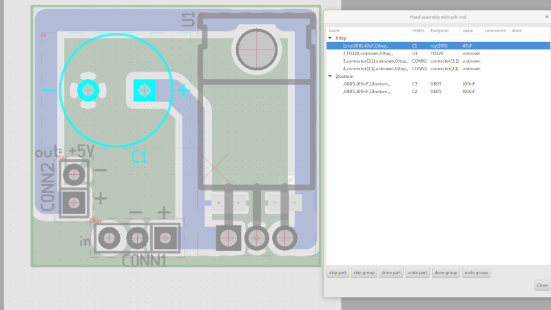
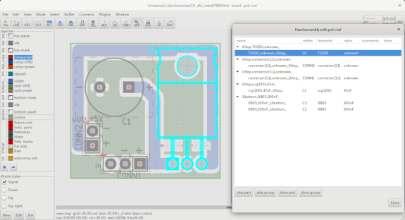
The asm window displays a table of components to the user with columns for name, refdes, footprint, value, comments, and done. Each component has a set of properties (side, x and y position, etc.) that are used to group and sort them.
Use the mouse pointer to select the first row within the asm window, the name consists of the comma separated list of subcircuit properties in the asm plugin config entry "0/top,T0220,unknown", described in detail later in parts 2 and 3 of the tutorial. The row just selected is the group row, and it contains only one part. In the pcb-rnd main window, the T0220 part should show as selected when the group row is selected.
Using the keyboard up and down arrow keys, move the selected row in the asm dialog window, and note that pcb-rnd highlights the entire group or the individual parts as they are selected in the asm window.
When the group is selected, all the parts within are selected on the design in the main window. When the part is selected, just that part is selected in the main window.
Now use the arrow keys or mouse pointer to select the single T0220 part in the first group of the 7805.lht design, and then use the mouse to click on the 'done part' button in the bottom of the asm window.
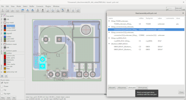
The asm window should now show that the T0220 part has 'yes' in the 'done' column, and the next available part is automatically highlighted in the asm window (this should be the row that reads "0/top,connector(2,1),unknown,"), causing the part comprising that group to be selected in the main window as well. If the group was selected instead of the part, and the user pressed the 'done group' button, the next group would be selected instead of the part.
As the user is assembling a pcb, they can proceed in this fashion, clicking on the 'done part' or 'done group' as they finish adding each part to the board. (If there is no other click in the asm dialog and the focus remains on a 'done' button, simply pressing the enter key will also work).
Click on 'done part' 3 more times, until the remaining selected part is the first one in the group that reads "1/bottom,0805,100nF,". Now move the mouse pointer over the main window and press the tab key to flip the view of the board to the opposite side. This group contains two parts, the 100nF capacitors C3 and C2. The first of these parts should show as selected. This is the one with the name "0805,100nF,,1/bottom,,"
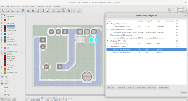
Click 'done part' twice more, completing the simulated build and the first part of this introductory tutorial.
2. Using the asm plugin group template with user defined attributes
In this section we show the user a simple way to define a new attribute (tolerance) for the capacitors in the 7805 based design (7805.lht), and this attribute will be then be used with the asm plugin.
We will use the object property editor to add attributes to the capacitors in the 7805 design and incorporate those attributes into the assembly plugin.
Open the 7805 design from pcb-rnd tutorials.
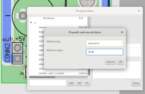
Let's start by specifying a 20% tolerance on part C1, the electrolytic filter cap that is placed between the 7805 input and ground. Note that moving the pcb-rnd cursor crosshairs to the origin of the footprint (the diamond drawn with red hairline), right clicking, and then selecting the property editor will likely open the property editor for the C1's positive padstack instead of the property editor for the whole subcircuit. To avoid this, adjust the crosshair to the X axis midpoint between the padstacks as shown below, and then right click and open the property editor. The property editor should identify itself as the subcircuit.
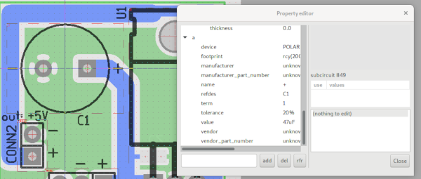
Use 'add' to add the new attribute to this subcircuit. The key will be 'tolerance' and the value field should have the desired string, use 20% there. The finished result of the property editor window is shown.
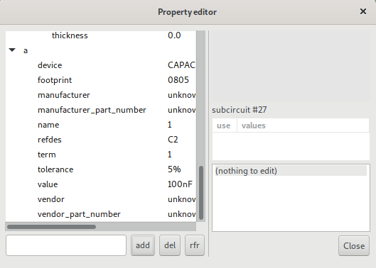
Following this, we will specify the same tolerance on the matching SMD filter
caps 5% to reduce part count. Press
Now all the capacitors in the 7805.lht example design have an additional user
defined 'tolerance' attribute with varying values. We will edit the template for
the assembly plugin in the pcb-rnd config tree to sort by this tolerance
value, and see how that changes the results in the assembly plugin.
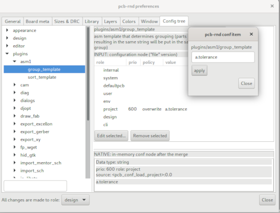
Enter the pcb-rnd preferences window, either by using the GUI (File>Preferences)
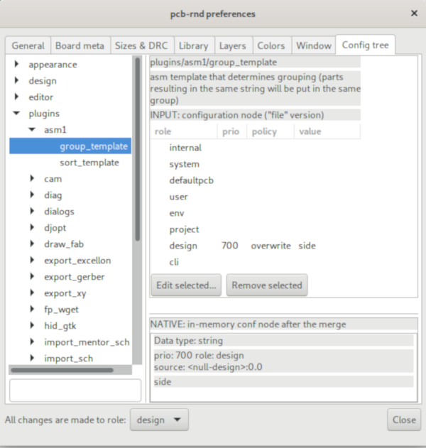
or the keyboard input {i c p}. Select the config tree submenu, and the asm1
plugin from the plugins subdirectory window. After expanding the submenu for
asm1 plugin, the user should see two items, a group_template and a
sort_template. Available settings and priorities for each role are shown in the
main window and the currently used setting is shown below that window. Note the
group_template is using the string:
Select the project role by clicking on it and click on 'Edit selected...'
button. Enter in "a.tolerance". Close the preferences window and summon the asm
plugin again from the command line {:} and entering asm.
In practice it is more useful to use multiple attributes and properties
(a list of comma separated words). For example on a board much bigger than
this example, appending a.tolerance to the original list would split
the original capacitor groups into further groups by their tolerance:
Often when soldering to assemble pcbs, certain parts must or should be
assembled in a precise order for a variety of reasons (space considerations
during assembly, thermal sinking considerations, group stage testing, or part
availability, to name a few).
In this section the user will define a new attribute for the top side parts of
the 7805 board and use it to prioritize a assembly build order. Give the top
side subcircuits new attributes with the new user defined key 'build_order' and
the value 1 for C1, 2 for U1, 3 for CONN1, and 4 for CONN2. This is a simple
example of ordering the sorting part for space considerations during assembly.
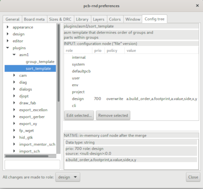
Using the pcb-rnd preferences, edit the asm1 plugin templates: create a new
rule in the design role of the asm1 group_template with the value 'side', and
create a new rule in the design role of the asm1 sort_template with the value
as shown in the screenshots below.
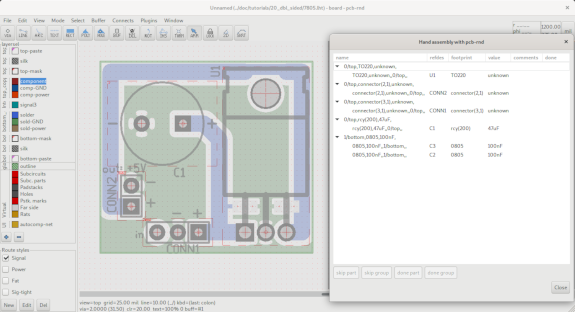
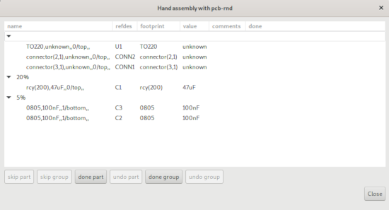
When asm is loaded, the assembly plugin dialog now shows the assigned part
order, shown in the screenshot below. If the user changes the build_order key
values for a footprint, and then reload asm, the parts will be sorted by the new
value.
side, a.footprint,a.value,a.asm::group
"side, a.footprint,a.value,a.asm::group,a.tolerance"
3. Using the asm sort template with user defined attributes
a.build_order,a.footprint,a.value,side,x,y